Post 28 has the same basic idea as my sheets, and one idea I should adopt. It also contains one claim I can’t reconcile with how cold-cathode tubes behave. I couldn’t retrieve the 0A4G datasheet numbers, so the tube-physics points below use analogous cold-cathode gas triodes. Please check them against the 0A4G datasheet before building.
Side by side
| Post 28 | My sheets 1–4 | |
|---|---|---|
| Role of the tube | Triggered impulse switch, with C_s dumped straight into the rods | Oscillator tube (R_c, C_c) that also drives the output |
| Starter bias | R_upper 2.2 MΩ + R_trim 2.2 MΩ + R_lower 10 MΩ from the C_s node | R_sb 1 MΩ to BLK, with a pulse through C_inj, D_inj and R_inj |
| Output | Anode node directly to the rod pair | Relay (S0–S2) or 24:1 transformer (S3–S6) |
| Rung timing | Nothing in the drawing sets it | C_c = 1/(f × 0.98 × R_c), 2:1 lock from the previous stage |
| Rung weights | Not shown | w_k from Ω, via R_w or R_sh |
| C_s | ≈ 47 V, film | 1000 µF / 63 V on the shared bus (relay rungs only) |
What I’d adopt
The starter divider is better than my R_sb. At 47 V it holds the starter at 32.6–38.5 V (trimmer fully in to fully out), just under threshold, so a small trigger pulse is enough. It is also tunable. Replace R_sb on Sheets 3 and 4 with it, and scale the divider ratio to the tube’s real starter breakdown voltage.
Where I think post 28 needs work
- Timing is missing. A stage triggered 1:1 by the previous stage fires at the same rate, so the octave ladder can’t form. R_lim with C_s does set a period (T ≈ R_lim·C_s·ln factor), which makes each stage the same oscillator as my S_k cell, with the output tapped at the anode instead of the cathode. Say so explicitly, and give R_lim a value, because it’s unspecified.
- 47 V is probably too low to fire the tube. CV2486, a cold-cathode gas triode of the same class, has a 73 V main-gap maintaining voltage and a 68 V control-gap breakdown, and the main-gap breakdown is 220 V. A Western Electric note for this tube class says the supply should sit between the breakdown and sustaining voltages. So the “few volts drop” claim doesn’t hold for glow-type tubes, and a 47 V C_s probably can’t conduct at all. Check the 0A4G’s own figures.
- “Dumps its entire energy” isn’t right. The tube extinguishes when the voltage reaches the maintaining level, not when C_s is empty. From 130 V down to 70 V it delivers 71% of the stored energy.
- Direct dump is current-limited. The cold-cathode analogs list maximum cathode currents of 1–35 mA. Average ping current in a self-oscillating stage is also limited to about 0.7 × the holding current, whatever C and R you choose. That’s why I put a step-down transformer in S3–S6.
One consequence for my own numbers
I took V_low = 30 V from your post 22, but if extinction really sits near 70 V, three things change:
- Timing factor: the ln factor drops from 0.981 to 0.693, so every C_c scales ×1.415 (S0 becomes 3.136 µF).
- Charge per ping: ΔV drops from 100 V to 60 V.
- Transformer ratio: S4 would then need 99% of a 24:1 transformer’s charge, so use 30:1 or higher.
Everything else in the tables stays the same. I’d measure V_fire, V_extinguish and holding current on your actual tube before trusting any of these.
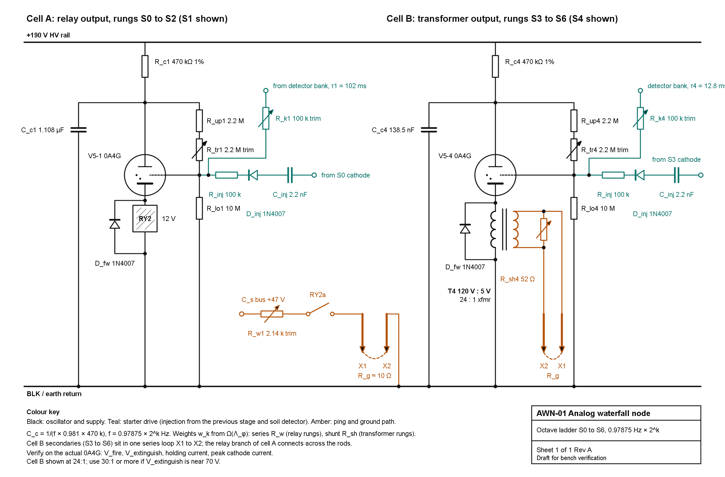
What’s drawn
- Cell A (S0–S2, S1 shown):
- Oscillator: 0A4G tube V5-1, 470 kΩ charging resistor R_c1 and 1.108 µF film capacitor C_c1.
- Starter: the post-28 divider (2.2 MΩ, 2.2 MΩ multi-turn trimmer, 10 MΩ), with 2:1 injection and detector coupling on the starter tap.
- Output: RY2 relay coil with a 1N4007 flyback diode, then the RY2a contact, the 2.14 kΩ weight trimmer R_w1 and the ground rods X1 and X2.
- Cell B (S3–S6, S4 shown): the same oscillator with a 120 V : 5 V (24:1) power transformer in the cathode, a 52 Ω shunt trimmer R_sh4 across the secondary, and the secondary in the rod loop.
- Wire colors: black for oscillator and supply, teal for the starter drive, amber for the ping and ground path.
Choices I made that you may want to change
- I kept the 130 V fire and 30 V extinguish values from your post 22. If your 0A4G actually extinguishes near 70 V, use the alternate values from my last reply and go to 30:1 or more on the transformer.
- The title block says “Draft for bench verification”. The 0A4G fire voltage, extinguish voltage, holding current and peak current still need checking on the real tube.
- The relay coil is drawn as “12 V”. Tell me the actual relay and I’ll relabel it.
AWN-01 Analog Waterfall Node BOM and Build Instructions.pdf (434.2 KB)
AWN-01 Analog Waterfall Node: BOM and Build Instructions
Rev A. Covers the schematic AWN-01 (cell A relay rungs, cell B transformer rungs), plus the modules it depends on: HV supply, 47 V ping bus, detector bank, ground system and logger. Values come from the design thread; items marked VERIFY are assumptions to confirm on the bench before you commit.
0. Read first: safety and assumptions
- 190 V DC is dangerous. Build the HV section in a grounded metal enclosure, one hand at a time, with a bleeder on every HV capacitor. Discharge and measure before touching anything.
- Mains isolation. Every supply here is fed from an isolating transformer. Never bond BLK (earth return) to mains ground or neutral.
- Ground rods. Call 811 (or your local locate service) before driving rods. Keep the ping rods at least 10 m apart and well away from the house grounding electrode, utilities and where people or pets stand. Peak ping current is about 1 A for about 5 ms on rung S0.
- Fuse every path. 2 A slow-blow in the rod loop, 100 mA on the 47 V feed, 50 mA fast on the HV rail.
- Unverified assumptions behind the numbers:
- Tube fires at 130 V and extinguishes at 30 V (from your post 22). If the 0A4G extinguishes near 70 V, multiply every C_c by 1.415 and use transformers at 30:1 or more.
- Earth resistance R_g = 10 Ω (model value) and relay contact dwell about 5 ms.
- Λ_φ is taken as written (absolute), giving the rung weights in section 4.
- The 0A4G base, peak cathode current and holding current have not been checked against the datasheet.
1. Module map
| Module | Ref prefix | Qty | What it does |
|---|---|---|---|
| Oscillator ladder | V5-k, R_ck, C_ck, divider | 7 (k = 0 to 6) | Relaxation stages at 0.97875 × 2^k Hz |
| 2:1 injection | C_inj, D_inj, R_inj | 6 (S1 to S6) | Locks each stage to the one before it |
| Relay output | RY1 to RY3 | 3 (S0 to S2) | Ping the rods from the C_s bus |
| Transformer output | T3 to T6 | 4 (S3 to S6) | Tube cathode drives a step-down transformer into the rod loop |
| Ping bus and ground | C_s, rods | 1 | 47 V reservoir, rods X1 and X2 |
| HV supply | PS-HV | 1 | 190 V DC rail |
| 47 V supply | PS-47 | 1 | Feeds C_s |
| Detector bank | D1 to D7 | 1 | Receives soil signal, drives each starter |
| Logger | DAQ | 1 | Waterfall and lock measurements |
2. Bill of materials
Ratings are minimums. Use film capacitors (polypropylene) for all timing and injection parts.
2.1 Oscillator ladder (per rung, seven rungs)
| Ref | Qty | Part | Value | Rating | Notes |
|---|---|---|---|---|---|
| V5-0 to V5-6 | 7 (+2 spare) | Cold-cathode gas triode | 0A4G | VERIFY base and ratings | |
| XV-0 to XV-6 | 7 | Tube socket | per datasheet | ||
| R_c0 to R_c6 | 7 | Resistor, metal film, 1% | 470 kΩ | 0.5 W, 350 V | Sets period with C_c |
| C_c0 to C_c6 | 7 sets | Film capacitor | see 2.2 | 400 V DC | Parallel sets, trim by measurement |
| R_up0 to R_up6 | 7 | Resistor, metal film, 1% | 2.2 MΩ | 0.5 W, 350 V | Starter divider top |
| R_tr0 to R_tr6 | 7 | Multi-turn trimmer | 2 MΩ | 0.5 W | Sets firing threshold |
| R_lo0 to R_lo6 | 7 | Resistor, metal film, 1% | 10 MΩ | 0.5 W, 350 V | Starter divider bottom |
| D_fw0 to D_fw6 | 7 | Diode | 1N4007 | 1000 V | Flyback across coil or primary |
2.2 Timing capacitors C_c (design values, 30 V extinguish case)
| Rung | Target f (Hz) | Target C_c | Build as (parallel) | Sum | Error |
|---|---|---|---|---|---|
| S0 | 0.97875 | 2216 nF | 2.2 µF + 15 nF selected | 2215 nF | -0.1% |
| S1 | 1.9575 | 1108 nF | 1 µF + 100 nF + 8.2 nF | 1108.2 nF | 0.0% |
| S2 | 3.915 | 554 nF | 470 nF + 82 nF + 2.2 nF | 554.2 nF | 0.0% |
| S3 | 7.83 | 277 nF | 270 nF + 6.8 nF | 276.8 nF | -0.1% |
| S4 | 15.66 | 138.5 nF | 100 nF + 39 nF | 139.0 nF | +0.4% |
| S5 | 31.32 | 69.3 nF | 68 nF + 1 nF | 69.0 nF | -0.4% |
| S6 | 62.64 | 34.6 nF | 33 nF + 1.5 nF | 34.5 nF | -0.3% |
Add a spare footprint on each rung for 1 nF, 2.2 nF and 4.7 nF trim pads. Final values are set by measuring the period (section 5, step 4), not by this table. If the extinguish voltage turns out near 70 V, the targets become 3136, 1568, 784, 392, 196, 98 and 49 nF.
2.3 Injection and coupling (S1 to S6)
| Ref | Qty | Part | Value | Rating |
|---|---|---|---|---|
| C_inj1 to C_inj6 | 6 | Film capacitor | 2.2 nF | 630 V |
| D_inj1 to D_inj6 | 6 | Diode | 1N4007 | 1000 V |
| R_inj1 to R_inj6 | 6 | Resistor | 100 kΩ | 0.5 W, 350 V |
S0 has no injection from a previous stage. It is the master and is entrained only by the soil detector. Each injection input connects to the previous stage’s cathode node (see schematic).
2.4 Relay output rungs (S0 to S2)
| Ref | Qty | Part | Value | Notes |
|---|---|---|---|---|
| RY1 to RY3 | 3 | Relay, SPST-NO, 12 V coil | contacts ≥ 2 A / 60 V DC | Coil about 400 Ω class, operate time ≤ 10 ms. VERIFY pull-in from the C_c pulse |
| R_w0 | 1 | Wirewound trimmer | 100 Ω, 2 W | Nominal 36 Ω |
| R_w1 | 1 | Wirewound trimmer | 5 kΩ, 2 W | Nominal 2.14 kΩ |
| R_w2 | 1 | Wirewound trimmer | 500 Ω, 2 W | Nominal 172 Ω |
2.5 Transformer output rungs (S3 to S6)
| Ref | Qty | Part | Value | Notes |
|---|---|---|---|---|
| T3 to T6 | 4 | Power transformer, 120 V primary | secondary 4 V to 5 V, ≥ 2 A | Ratio ≥ 24:1, 30:1 preferred. A 6.3 V (19:1) part is too low for S4 |
| R_sh3 | 1 | Wirewound trimmer | 10 Ω, 2 W | Nominal 3.0 Ω |
| R_sh4 | 1 | Wirewound trimmer | 100 Ω, 2 W | Nominal 52 Ω |
| R_sh5 | 1 | Wirewound trimmer | 25 Ω, 2 W | Nominal 10.3 Ω |
| R_sh6 | 1 | Wirewound trimmer | 50 Ω, 2 W | Nominal 14.7 Ω |
The 120 V winding is the primary (in the tube cathode circuit). The low-voltage winding goes in the rod loop. The pulses stay within a 60 Hz core’s volt-second rating (0.16, 0.08, 0.04, 0.02 V·s for S3 to S6, against about 0.45 V·s usable).
2.6 Ping bus, rods and protection
| Ref | Qty | Part | Value | Notes |
|---|---|---|---|---|
| C_s | 1 | Electrolytic, low ESR | 1000 µF, 63 V | Shared reservoir for RY1 to RY3 |
| R_ch | 1 | Resistor | 100 Ω, 2 W | Charge limit from the 47 V supply |
| F1 | 1 | Fuse, slow-blow, with holder | 2 A | In the rod loop |
| F2 | 1 | Fuse | 100 mA | On the 47 V feed |
| X1, X2 | 2 | Copper-clad ground rod | 5/8 in x 8 ft | Spaced ≥ 10 m |
| 2 | Rod clamps | |||
| 1 | Direct-burial wire | #10 AWG, length to suit | ||
| X3, X4 | 2 | Receive electrodes | non-polarizing Cu/CuSO4 recommended | Separate from ping rods. Steel rods polarize and add ELF noise |
2.7 HV supply, 190 V DC (optional if you already have the post-16 B+ supply)
| Ref | Qty | Part | Value |
|---|---|---|---|
| T_iso | 1 | Isolation transformer, 120:120 | ≥ 50 VA |
| D_a, D_b | 2 | Diode | 1N4007 |
| C_a | 1 | Capacitor | 22 µF, 250 V |
| C_b | 1 | Capacitor | 22 µF, 450 V |
| Q1 | 1 | NPN pass transistor | MJE340 (300 V), heatsink |
| Z1, Z2 | 2 | Zener | 1N5387B (180 V, 5 W) + 1N4740A (10 V, 1 W) in series |
| R_bias | 1 | Resistor | 15 kΩ, 3 W |
| C_out | 1 | Capacitor | 10 µF, 250 V |
| R_bleed | 1 | Resistor | 100 kΩ, 2 W |
| F_HV | 1 | Fuse, fast | 50 mA |
Half-wave doubler (D_a, D_b, C_a, C_b) gives about 330 V unloaded. Q1 as an emitter follower from the zener stack gives about 189 V. Expect about 3.5 W in Q1 at 25 mA.
2.8 47 V supply
| Ref | Qty | Part | Value |
|---|---|---|---|
| T_47 | 1 | Transformer | 120 V to 36 V AC, 1 A |
| BR1 | 1 | Bridge rectifier | 3 A, 100 V |
| C_47 | 1 | Capacitor | 4700 µF, 63 V |
No regulation is needed. About 45 to 48 V, and the R_w and R_sh trims absorb the difference.
2.9 Detector bank (new design, prototype on a breadboard first)
This is not from your posts. It replaces the earlier detector box so the coupling strength can be set per rung.
| Ref | Qty | Part | Value | Notes |
|---|---|---|---|---|
| U_in | 1 | Instrumentation amp | INA128, gain resistor 49.9 Ω (G ≈ 1000) | AC-coupled input |
| Cin_a, Cin_b | 2 | Film capacitor | 10 µF, 63 V | Input coupling |
| Rb_a, Rb_b | 2 | Resistor | 10 MΩ | Input bias to analog ground |
| U_bpf0 to 6 | 4 | Quad op-amp | TL074 | 7 band-pass + 7 rectifier sections use 14 of 16 |
| BPF parts | 7 sets | see 4.3 | Q = 2, unity gain | |
| Rect parts | 7 sets | 1N4148 x2, 10 kΩ x3 | Half-wave precision rectifier | |
| R_d | 7 | Resistor | 100 kΩ | Detector averaging |
| C_d | 7 | Film capacitor | see 4.4 | tau = T/5 |
| U_cmp | 4 | Dual comparator | LM393 | One section per rung |
| Thr | 7 | Trimmer | 10 kΩ | Detection threshold |
| OC0 to OC6 | 7 | Opto, V_CEO ≥ 300 V | TLP627-1 class | VERIFY part and rating |
| R_k0 to R_k6 | 7 sets | 100 kΩ fixed + 2 MΩ multi-turn in series | Sets starter pulse (the coupling K) | |
| PS-AN | 1 | ±12 V analog supply | 12-0-12 V transformer + 7812/7912 | Tie analog ground to BLK at one point only |
Each opto output transistor connects collector to +190 V and emitter through R_k to that rung’s starter tap.
2.10 Logger and test tap
| Ref | Qty | Part | Value |
|---|---|---|---|
| DAQ | 1 | 24-bit ADC board, ≥ 8 channels | sample at 512 Hz or 2048 Hz |
| 1 | Single-board computer or laptop for capture | battery or isolated supply | |
| Tap R1, R2 | 7 each | Resistor | 1 MΩ and 10 kΩ divider from each cathode node |
| Tap Z | 7 | Zener | 5.1 V clamp at the ADC input |
| Rsense | 1 | Resistor | 1 Ω, 1%, 2 W (in the rod loop for current checks) |
2.11 Hardware and tools
Grounded aluminum chassis, HV-rated standoffs, HV wire (≥ 600 V), safety labels, 100:1 HV scope probe, oscilloscope, frequency counter, multimeter, resistor and capacitor substitution boxes, and a variable HV bench supply for tube characterization.
3. Rung weight tables
Ping charge rule: Q_k = w_k × I_u / f_k, with I_u = 5 mA and w = Ω(f) as written.
| Rung | f (Hz) | w_k | Q_k (µC) | Weight element | Nominal |
|---|---|---|---|---|---|
| S0 | 0.97875 | 0.942 | 4810 | R_w0 series | 36 Ω |
| S1 | 1.9575 | 0.043 | 110 | R_w1 series | 2.14 kΩ |
| S2 | 3.915 | 0.996 | 1270 | R_w2 series | 172 Ω |
| S3 | 7.83 | 0.239 | 153 | R_sh3 shunt | 3.0 Ω |
| S4 | 15.66 | 0.874 | 279 | R_sh4 shunt | 52 Ω |
| S5 | 31.32 | 0.529 | 84.5 | R_sh5 shunt | 10.3 Ω |
| S6 | 62.64 | 0.619 | 49.4 | R_sh6 shunt | 14.7 Ω |
These assume R_g = 10 Ω and 5 ms contact dwell. Trim to the measured Q_k, not the nominal resistor value.
4. Detector bank values
4.1 Architecture
X3/X4 receive electrodes → AC coupling → INA128 → seven parallel channels, one per rung: band-pass, precision rectifier, averaging RC, comparator, opto, R_k, starter tap.
4.2 Why these choices
Band-pass Q = 2 suits octave-spaced rungs. The averaging time constant is T_k/5, which keeps the “0.2 s tail” ratio from your post-22 detector. The opto isolates the 190 V starter side from the op-amps.
4.3 Band-pass (multiple-feedback, C1 = C2 = C, unity gain, Q = 2)
| Rung | f_k (Hz) | C | R1 | R2 | R3 | Resulting f0 |
|---|---|---|---|---|---|---|
| S0 | 0.979 | 2.2 µF | 147 kΩ | 21.0 kΩ | 294 kΩ | 0.984 |
| S1 | 1.958 | 1.0 µF | 162 kΩ | 23.2 kΩ | 324 kΩ | 1.963 |
| S2 | 3.915 | 470 nF | 174 kΩ | 24.9 kΩ | 348 kΩ | 3.889 |
| S3 | 7.83 | 220 nF | 187 kΩ | 26.1 kΩ | 374 kΩ | 7.817 |
| S4 | 15.66 | 100 nF | 205 kΩ | 28.7 kΩ | 402 kΩ | 15.82 |
| S5 | 31.32 | 47 nF | 215 kΩ | 30.9 kΩ | 432 kΩ | 31.34 |
| S6 | 62.64 | 22 nF | 232 kΩ | 33.2 kΩ | 464 kΩ | 62.32 |
Resistors are E96, 1%. Use film or C0G capacitors. If a center frequency lands off, adjust R3 first.
4.4 Averaging capacitors (R_d = 100 kΩ)
| Rung | tau target | C_d |
|---|---|---|
| S0 | 204 ms | 2.2 µF |
| S1 | 102 ms | 1 µF |
| S2 | 51 ms | 470 nF |
| S3 | 25.5 ms | 220 nF |
| S4 | 12.8 ms | 120 nF |
| S5 | 6.4 ms | 68 nF |
| S6 | 3.2 ms | 33 nF |
5. Build instructions
Step 1. Bench power. Build the 47 V supply and the HV supply (or confirm your existing B+ gives 190 V at ≥ 25 mA). With a dummy load, confirm 190 V ± 5 V and 45 to 48 V. Check the bleeders drop HV below 30 V within a minute of power-off.
Step 2. Characterize the tubes. For each 0A4G, wire a test oscillator: 190 V → 470 kΩ → tube anode, 1 µF to BLK, cathode to BLK through 100 Ω, starter through your R_up/R_tr/R_lo divider. Measure with a 100:1 probe (a 10:1 probe loads a 470 kΩ node by about 4.5%). Record V_fire, V_extinguish (valley), period, and starter breakdown. Compute C_c for any target period with C = T / (R_c × ln((HV − V_low)/(HV − V_fire))). Match tubes into rungs by similar V_fire. If V_extinguish is near 70 V, switch every value to the alternate set in 2.2 and use transformers ≥ 30:1.
Step 3. Build S0 alone. Wire R_c0, C_c0, V5-0, the starter divider, RY1 and D_fw0. Do not yet connect the rods. Set R_tr0 so the tube fires reliably. Measure the period over 50 cycles with the counter and adjust C_c0 trim pads until the frequency is 0.97875 Hz ± 0.2%.
Step 4. Build S1 to S6 free-running. For each rung, tune C_ck so the free-run period is 1% to 3% longer than half the previous rung’s period (2:1 lock requires the driver pulse to arrive before the stage would fire on its own). Measure each over 50 cycles.
Step 5. Enable injection and verify lock. Connect C_inj, D_inj, R_inj from each previous cathode node. Check that each stage now runs at exactly twice the previous rung’s rate. Fine-tune C_ck until the half-rate sideband on the stage’s line is as small as it can be while the lock holds.
Step 6. Wire the outputs. Cell A: add RY1 to RY3, R_w trimmers and C_s with R_ch and F2. Cell B: add T3 to T6, R_sh trimmers and F1. Rods stay disconnected. Replace them with a 10 Ω, 5 W dummy load, and a 1 Ω sense resistor in series.
Step 7. Calibrate weights. For each rung, record the sense-resistor voltage on the scope, integrate current over one ping to get Q_k, and trim R_w or R_sh until Q_k matches section 3. Cell B secondaries sit in one series loop X1 → T3 → T4 → T5 → T6 → X2. The cell A relay branch connects across the rods, not in the loop.
Step 8. Build the detector bank. Build and test one channel on a breadboard first. Inject a known sine at each f_k through a 1000:1 attenuator and confirm the band-pass center, the averaging RC and the comparator threshold. Then build all seven. With the opto output disconnected from the starter, set R_k fully out. Connect, then raise the pulse (lower R_k) until a detected input fires the stage, and finally back off so it just fails, then add about 20% margin.
Step 9. Dummy-soil test with two nodes. Build a second node. Replace the rods with 10 Ω each and a 100 kΩ coupling resistor between the two. Run ratio sweeps by changing node B’s C_c0: 2.2 µF (ratio 1), 3.3 µF (1.5), 3.567 µF (1.618), 4.4 µF (2). Log at least 50 cycles per setting.
Step 10. Install the ground system. Drive X1 and X2 at least 10 m apart, and X3/X4 at least 10 m from them and from each other. Measure R_g with a ground tester and re-trim the weights to hit Q_k. Fit F1.
Step 11. Log the waterfall. Sample at 512 Hz (or 2048 Hz for comparability with earlier runs). Use a 128 s Hann window and an 8 s hop. Also log the S0 ping times for the phase waterfall (one row per cycle, one column per node). Lock criterion: coefficient of variation of the inter-node ping phase below 0.05 over at least 50 cycles.
6. Acceptance tests
| Test | Pass condition |
|---|---|
| S0 period | 0.97875 Hz ± 0.2% |
| Ladder ratios | Each rung exactly 2× the previous over 50 cycles |
| Ping charge | Measured Q_k within ±10% of section 3 |
| Detector | Each channel fires its starter only at its own f_k |
| Two-node lock | Ratio 1.0 and 2.0 lock (CV < 0.05); log 1.5 and 1.618 |
| Mains | No lock of S6 to 60 Hz hum with the antenna connected |
7. Troubleshooting
| Symptom | Likely cause | Fix |
|---|---|---|
| Tube latches on | R_c too small for the holding current | Raise R_c |
| Tube never fires | HV below breakdown, or starter bias too low | Check 190 V, lower R_tr |
| Stage won’t divide-lock | Free-run period outside 1 to 3% window | Re-tune C_ck |
| Relay doesn’t pull in | C_c pulse too weak for the coil | Raise C_c or use a more sensitive relay |
| S6 follows 60 Hz | Hum entering the detector | Shield, narrow the S6 band-pass, or move the electrodes |
| Transformer rung weak | Saturation or low ratio | Use ≥ 30:1, check volt-seconds |
8. Known unknowns
The 0A4G fire and extinguish voltages and holding and peak current; the base pinout; relay pull-in from an impulse; the real earth resistance and contact dwell; the detector bank’s sensitivity (new design, not bench-tested); and which Λ_φ convention best matches the measured lock ranges.