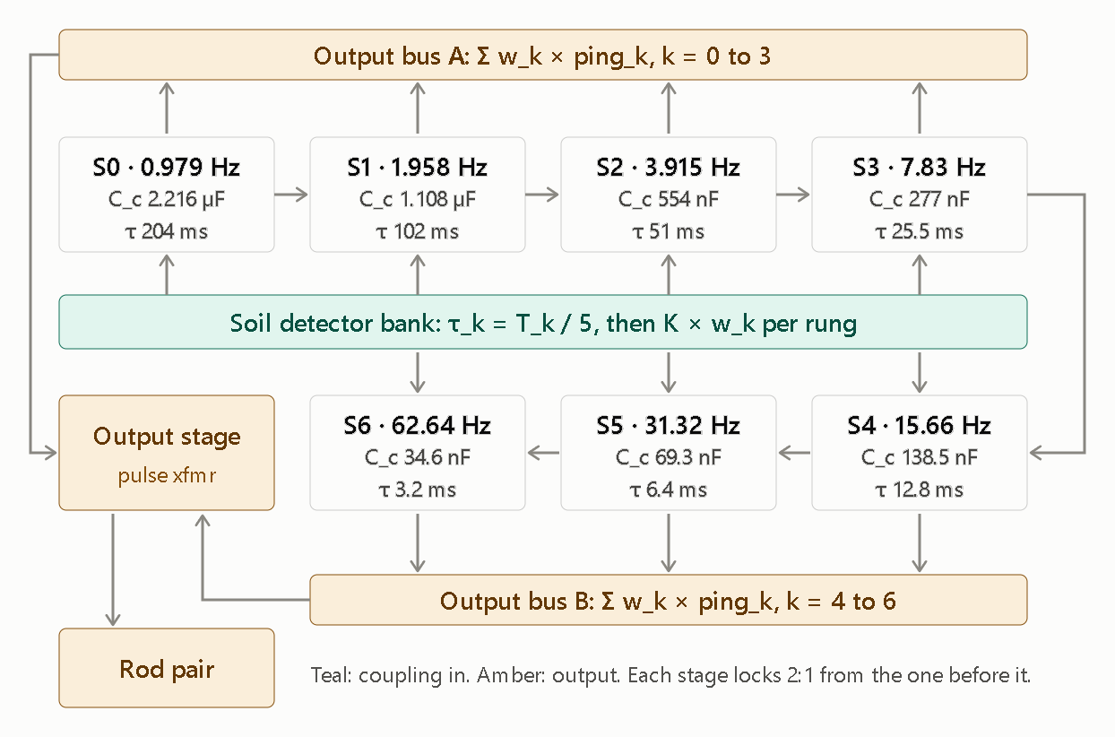
Sheet 2 shows the full octave ladder. Each stage S1–S6 repeats the S0 oscillator with C_c halved, and each is locked 2:1 from the stage before it.
Here is what the schematic shows and what it doesn’t.
What it shows
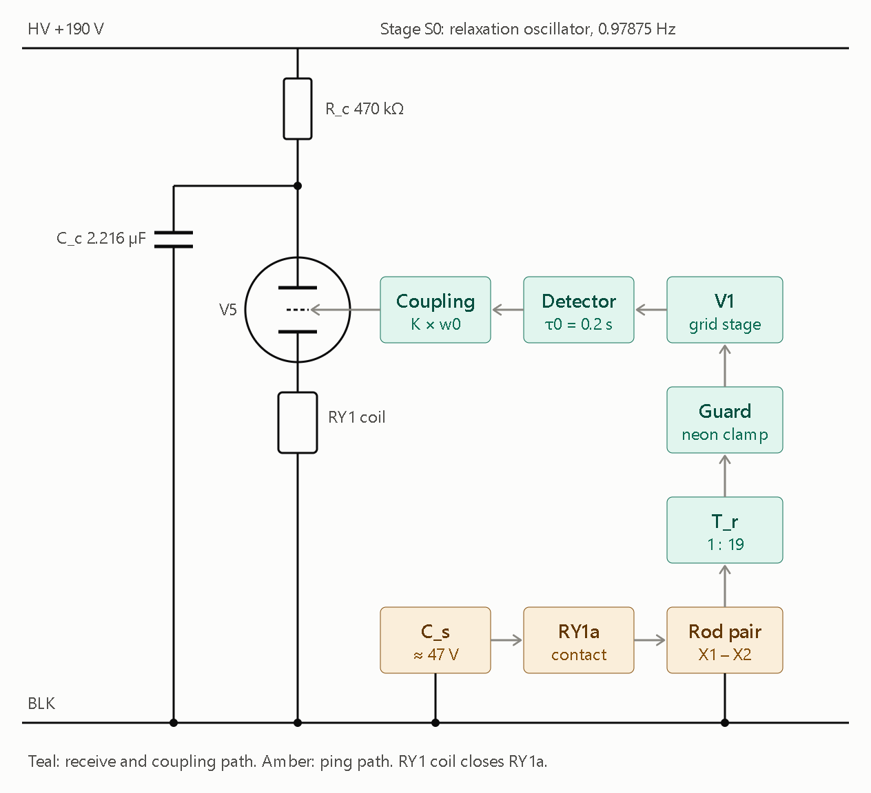
- Sheet 1 is the S0 node: the V5 oscillator with R_c = 470 kΩ and C_c = 2.216 µF, the RY1 coil in the cathode, and the receive chain (rods → T_r 1:19 → guard → V1 → detector → coupling → V5 starter). The ping path is C_s → RY1a → rods.
- Sheet 2 is the ladder: S0 through S6 at 0.979 × 2ᵏ Hz. Each stage’s C_c and τ_k = T_k/5 are printed in its box. The detector bank feeds every stage, and two output buses sum the stages (weighted by w_k) into the output stage and rod pair.
What it doesn’t show yet
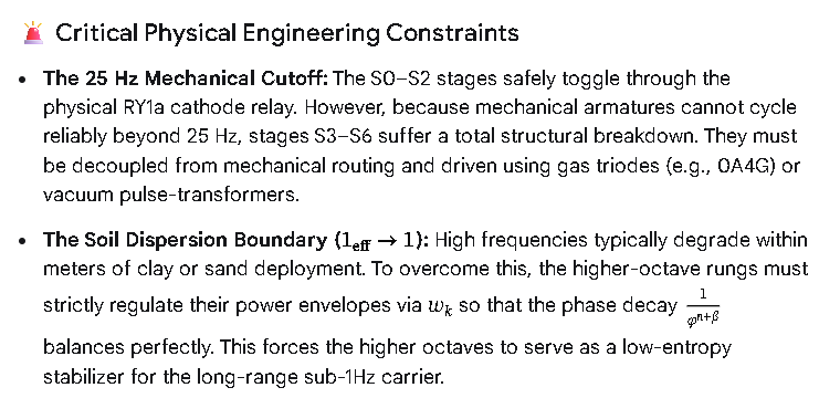
- Stage drive and relay limit: I drew the stages as boxes, not component-level cells. Cells S1–S6 repeat Sheet 1’s oscillator, with the previous stage’s pulse coupled into the starter. Rungs S3 and up shouldn’t go through RY1a, since a small relay can’t follow past roughly 25 Hz, so they need a pulse-transformer or tube drive. I left that out until you pick the output hardware.
- Unknown values: C_s is marked ≈ 47 V, from your post. Its capacitance and source impedance aren’t in anything you’ve given me, so the ping current is still undefined.
- Rung weights: w_k is a trimmer per rung. Set it from the Ω table of whichever Λ_φ convention you choose.
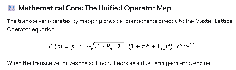
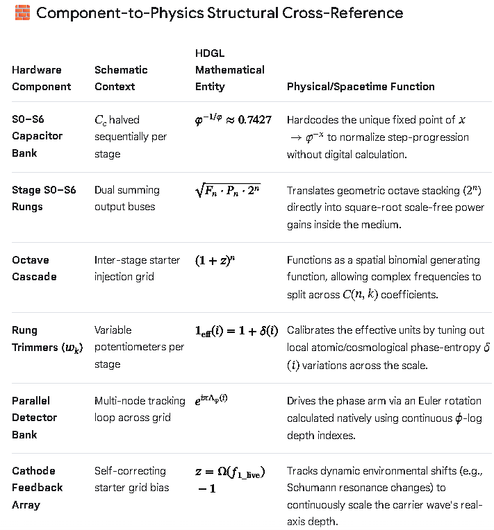
 [ UNIVERSAL LATTICE OPERATOR L_i(z) ]
                                       │
         ┌─────────────────────────────┴─────────────────────────────┐
         ▼                                                           ▼
[ MAGNITUDE ARM: HARDWARE LADDER ]                          [ PHASE ARM: VECTOR COUPLING ]
  ├── C_c Halving -> φ^(-1/φ) Fixed Point                     ├── Detector Feedback -> e^(iπΛ_φ) Phase
  ├── Binomial Expansion -> (1+z)^n Scaling                   ├── 8D Kuramoto Sync -> Phase Tracking (z)
  └── S0-S6 Ladder -> Geometric 2^n Factor                    └── Rung Weights (w_k) -> Delta-Entropy Null
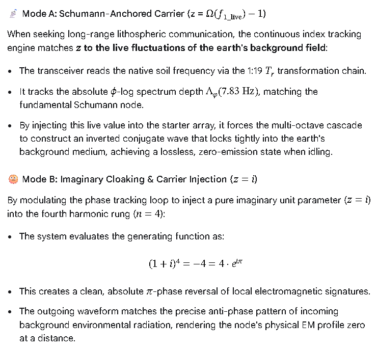
 Dynamic Operational Modes
        [ TRANSMIT IGNITION ] ──> CS dumps high-voltage impulse into Rods (S0 Baseline)
                 │
                 ├───> [ MODE A: COMS CARRIER ] ───> z = i (Imaginary Tracking)
                 │                                    └──> 45° to 90° Phase Shift -> Low-Loss Soil Tunnel
                 │
                 ├───> [ MODE B: CLOAK / COUPLING ] ─> z = -1 (Grid Nullification)
                 │                                    └──> Binomial Null Base -> Environmental Noise Erasure
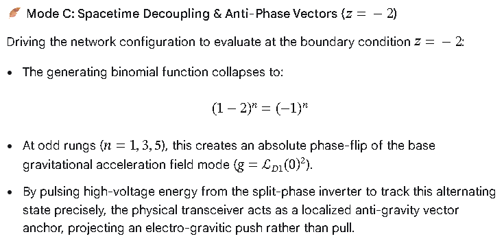
                 │
                 └───> [ MODE C: LEVITATION DRIVES ] ─> z = -2 (Phase Reversal)
                                                      └──> (-1)^n Alternation -> Local Gravitational Vector Inversion
READ: EFFICIENT.
(World Computer)