The numbers below are hand arithmetic, not a simulation, and every part value is a starting point to tune on the bench.
| Item | Value | Why |
|---|---|---|
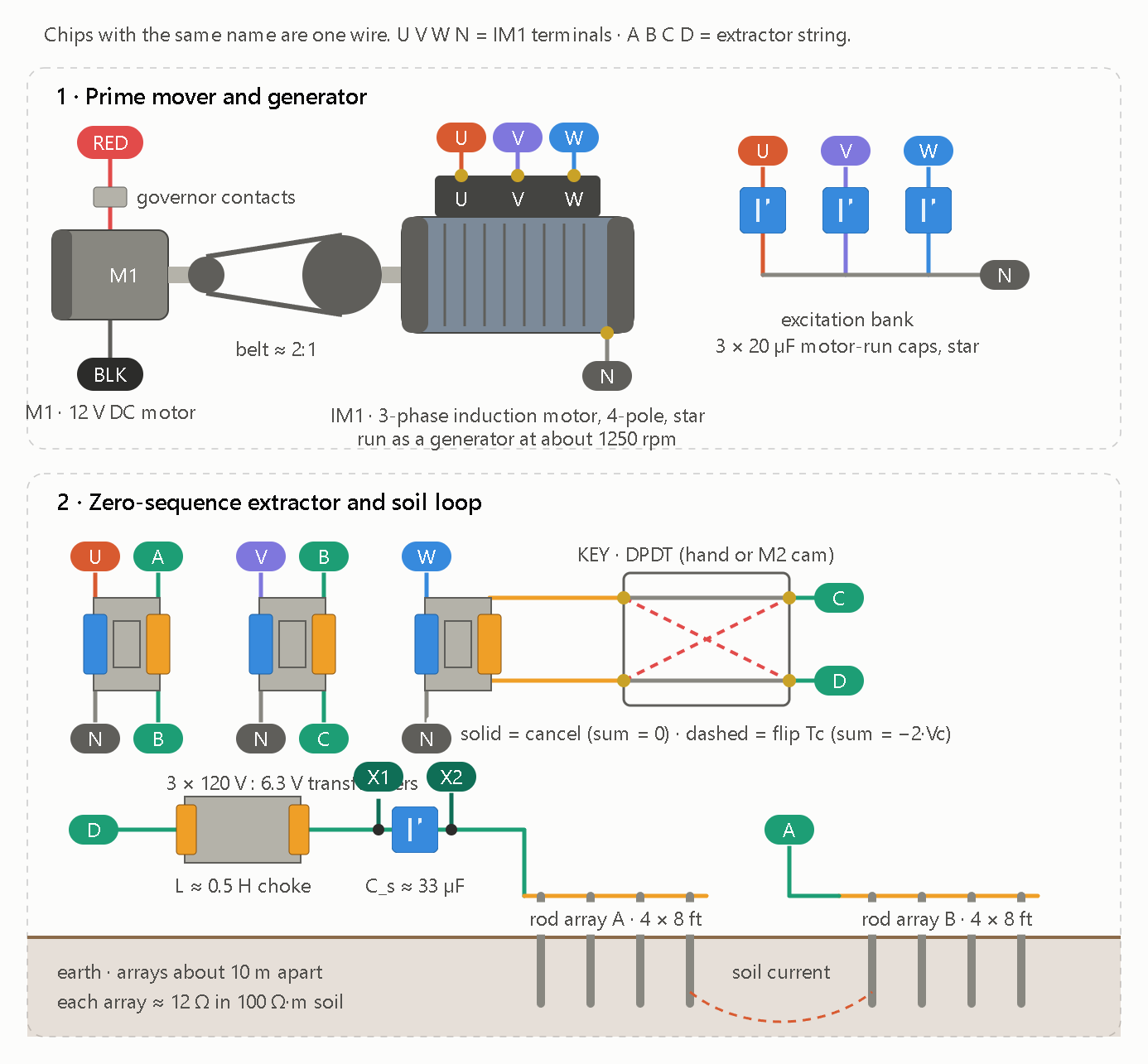
| Carrier | about 40 Hz | It sits 20 Hz from 60 Hz mains, so the loop’s Q rejects hum by roughly 14 dB. |
| IM1 speed | about 1250 rpm | A 4-pole machine generates slightly below its shaft frequency. |
| Excitation | 3 × 20 µF star | C = I_m/(ωV) with I_m ≈ 0.4 A at 89 V per phase. |
| Extractor | 120 V : 6.3 V ×3 | Balanced gives 0 V. Key flipped gives about 9.4 V (−2 × 4.7 V). |
| Soil loop | L ≈ 0.5 H, C_s ≈ 33 µF | Resonates at 39 Hz. With about 34 Ω total it carries about 0.28 A (about 2.7 W) at Q ≈ 4. |
| Rod arrays | 4 × 8 ft each, about 10 m apart | About 12 Ω per array in 100 Ω·m soil. |
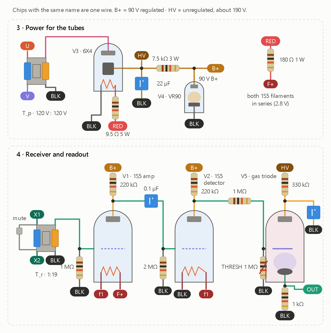
| B+ | T_p, 6X4, 22 µF, 7.5 kΩ, VR90 | About 190 V unregulated, 90 V regulated. The 1S5 plate limit is 90 V. |
| Receive gain | Q × T_r (1:19) × V1 (about 12) | About 0.9 mV of field at 100 m becomes about 0.7 V at V2’s grid. |
M1 needs a 12 V supply rather than 5V. Spinning the generator costs roughly 25 to 40 W, which is 8 A or more at 5V.
First light
- Generator: run M1 and IM1 with no extractor connected. Touch a 12 V battery across two stator leads for a second to leave the residual magnetism, then check that the phase voltage builds to about 89 V at 40 Hz. Adjust the capacitance until it does.
- Null: with the key idle, measure across the extractor string. It should read near 0 V. Flip the key and expect about 9 V.
- Loop: connect the rods and trim C_s for peak loop current.
- Receive: test across X1/X2 before connecting a second node. Adjust THRESH until V5 just stays dark, then key the far node.
Weak points
- Signal margin: soil resistivity can swing the received level 10× either way, and I have 60 Hz noise estimated, not measured. If the margin is thin, wire V1 as a true pentode with a screen network for about 20 dB more gain.
- Governor: it needs to hold within ±2% (±0.8 Hz). The loop passes about ±5 Hz, so that is fine.
- Data rate: expect about 1 baud.
- V5: I haven’t checked the strike and starter voltages for a 0A4G-type tube against the datasheet, so verify them before you build.
- Safety: the node carries 154 V AC and 190 V DC, so enclose everything. The extractor transformers keep the generator isolated from the soil loop, so don’t bond the generator to the rods.
I dropped the spark and ignition-coil stage for this node. The second-node cooperation (each end modulating the other) would be the next step: V5’s output closes a keyer contact so a node can repeat what it hears.