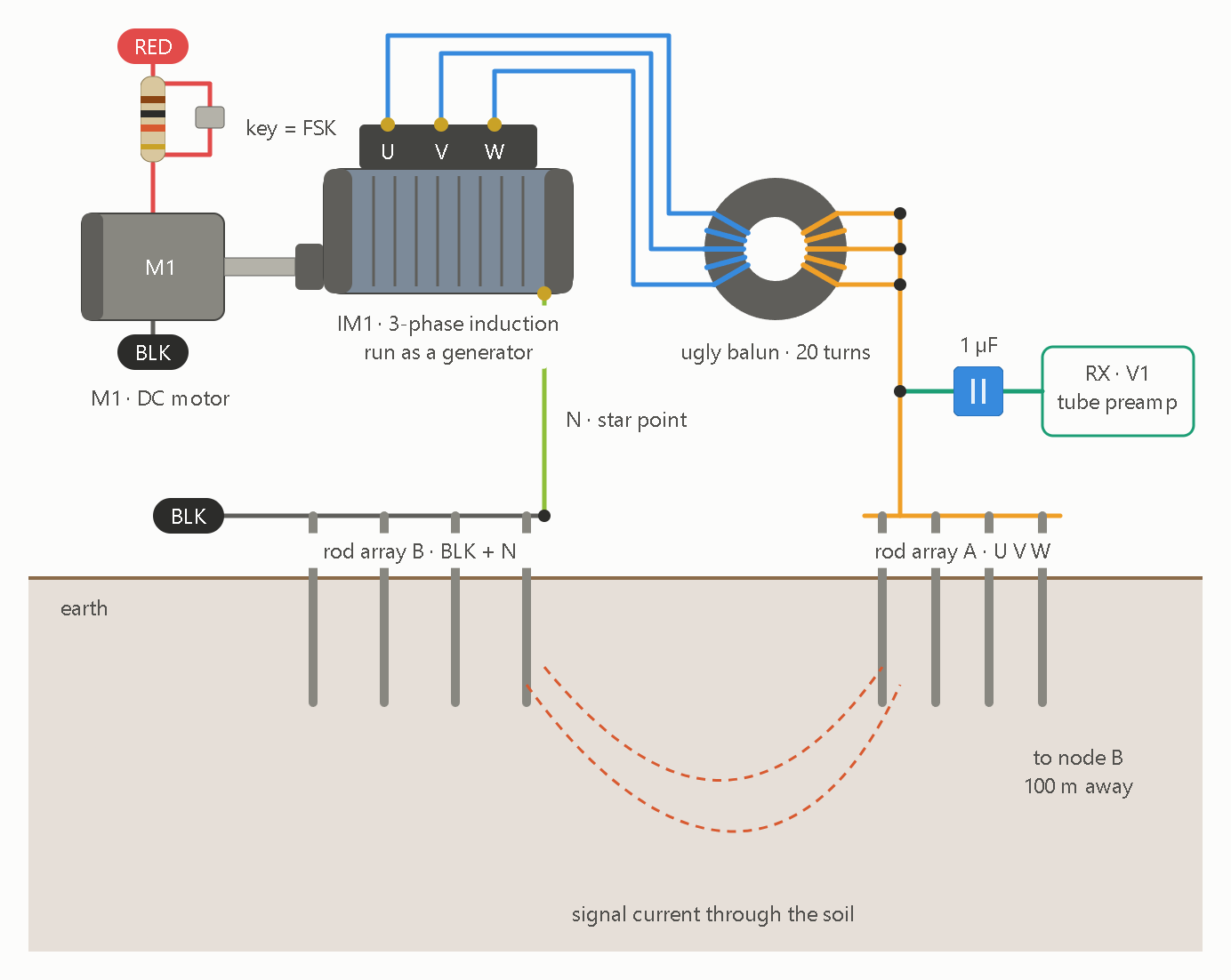
Here is how the drawing works, followed by the points that matter for building it.
Signal path. M1’s supply runs through a speed network with a key. The key shorts out part of that resistance, which shifts the speed and therefore IM1’s frequency, so keying gives FSK. U, V and W go through the 20-turn balun and are tied to rod array A. The star point N goes to rod array B, which is also the black lead. Current runs through the soil between the two arrays. The stage-1 tube preamp stays connected across the same rods at high impedance, so it listens while the node transmits. The node on the other end is a mirror image.
Because the balun forces U, V and W to carry equal current, the output is the zero-sequence part of the three phases, and that is what carries the signal. Cancellation by itself doesn’t raise efficiency. What couples into the soil is the small residual, so the design should create that residual on purpose.
Resonance is a tuning job in the hardware. The balun’s inductance, the electrode and soil resistance, and a series capacitor form a resonant loop at f = 1/(2π√LC). For example, a 10 mH balun needs about 1 mF to resonate at 50 Hz. Paralleled motor-run capacitors are the natural analog part for that. Your identity N = Ω·C²/(m·s) is dimensionally correct for the ohm, but it’s a units identity and doesn’t produce resonance on its own. The script’s Ω (m²/s⁷) is also a different quantity from the ohm. Separately, emergentC1.py multiplies the constants by an assumed 1.05, so its 5% change is an input, not a result.
hdgl_tte_protocol.ino is the digital version of this link. An AD9833 DDS does FSK at ±0.1 Hz around 3.915 Hz with Hamming-coded 4-bit frames. The receive side is a stub, and its comments say “Simulate reception”.
That raises a design issue for the motor version. At a 50 Hz carrier, ±0.1 Hz is about 0.2% of speed, roughly 3 rpm on a 4-pole machine. A 5V DC motor behind a series resistor won’t hold that, so M1 needs tach feedback or a mechanical governor. A 3.9 Hz carrier is worse. An induction generator at that frequency barely self-excites, because voltage scales with frequency and the excitation capacitance grows as 1/f².
Should the carrier be the motor’s own ~50 Hz, with the Schumann sub-harmonics as the modulation as in our waterfall sim, or the 3.9 Hz range from the Arduino?