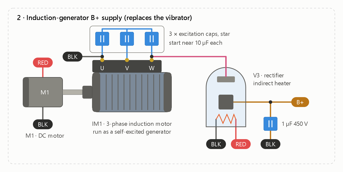
This replaces the whole vibrator in stage 2 (M1 plus the points, T1 and the old rectifier). Stages 1, 3 and 4 stay as drawn.
M1 spins the induction motor above its synchronous speed, with a small capacitor bank on its terminals. That makes it a self-excited induction generator. The rotor’s residual magnetism seeds the field, and the capacitors let the AC voltage build up. V3 then rectifies one winding (U to W) into B+. There are no contacts to burn, and the frequency comes from rotor speed, so the saturation problem I hit with the ferrite toroid goes away.
- Size sets the power draw. A no-load induction generator still has to supply its own core and friction losses, and those grow with motor size. The spark stage draws almost no energy, so use the smallest 3-phase induction motor you can find. A 1/4 hp unit could pull 60 to 100 W just spinning, which is 12 A or more from 5V.
- Speed matters more than torque. M1 has to hold the rotor above the motor’s synchronous speed (for a 4-pole motor on 60 Hz, 1800 rpm). A 5V DC motor needs a gear step-up to do that.
- The capacitor value is a starting guess. Too little and the voltage never builds, and too much and it overshoots toward the winding’s insulation limit. Expect to tune it with a meter. Touching the motor leads briefly with a battery before the first spin can help leave the residual magnetism the field needs to start.
- Output voltage follows the nameplate. A 230 V motor can give a few hundred volts peak, so I rated the filter cap at 450 V. Stage 3’s 0.1 µF capacitor then stores more energy, which makes the gas triode’s peak-current limit tighter.
- V3’s heater needs care. The heater is fed from the 5V rail while the cathode sits at B+. Pick an indirectly heated rectifier with a heater-to-cathode rating well above your B+. A 6.3 V type will run slightly underheated at 5V, which is fine at this tiny current.