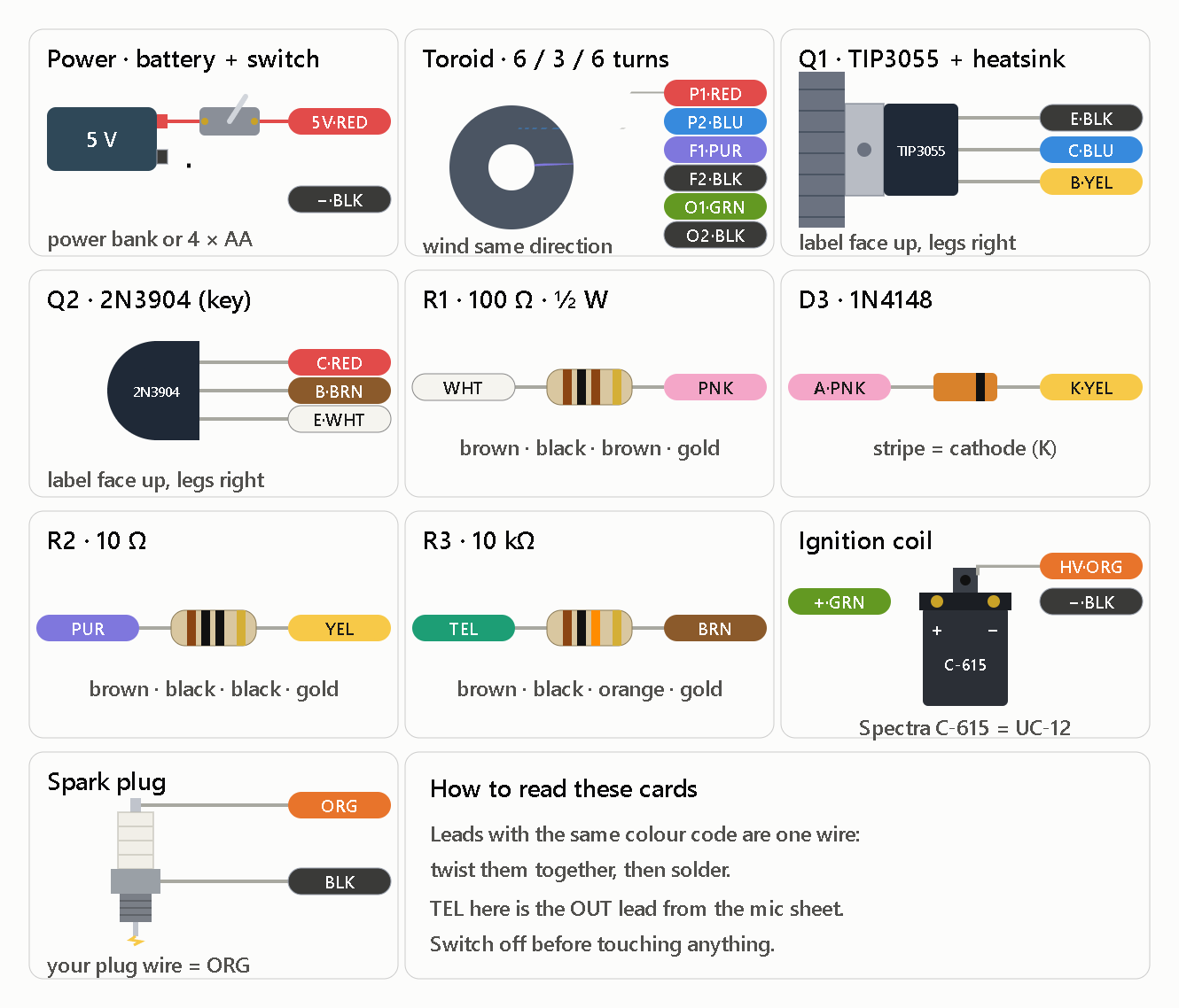
Sheet 1
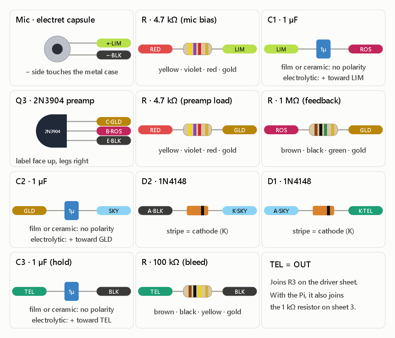
Sheet 2 is the microphone sound switch. It works with or without the Pi, and its TEL lead is the OUT connection.
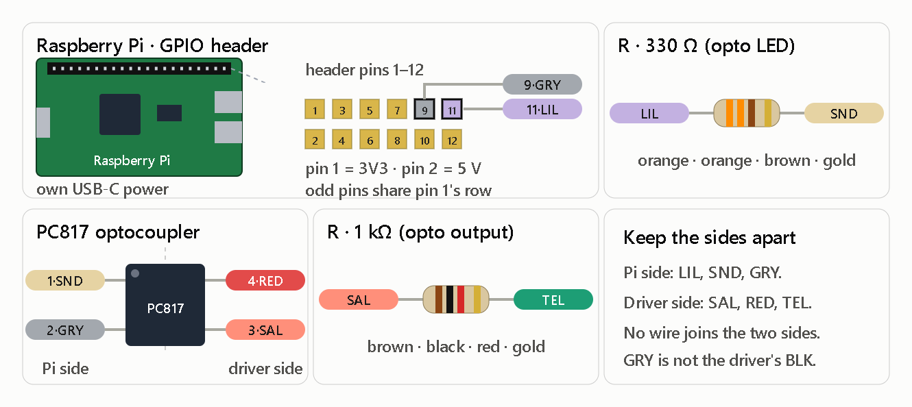
Sheet 3 is the optional Pi add-on. It joins through TEL and RED and shares no ground with the driver.
Without the Pi, build sheets 1 and 2. With the Pi, build all three. Sheet 3 only adds parts and doesn’t change anything on the other two.
Build order
- Wind the toroid and build sheet 1 alone. Use a ferrite toroid (6, 3 and 6 turns), not the inverter core.
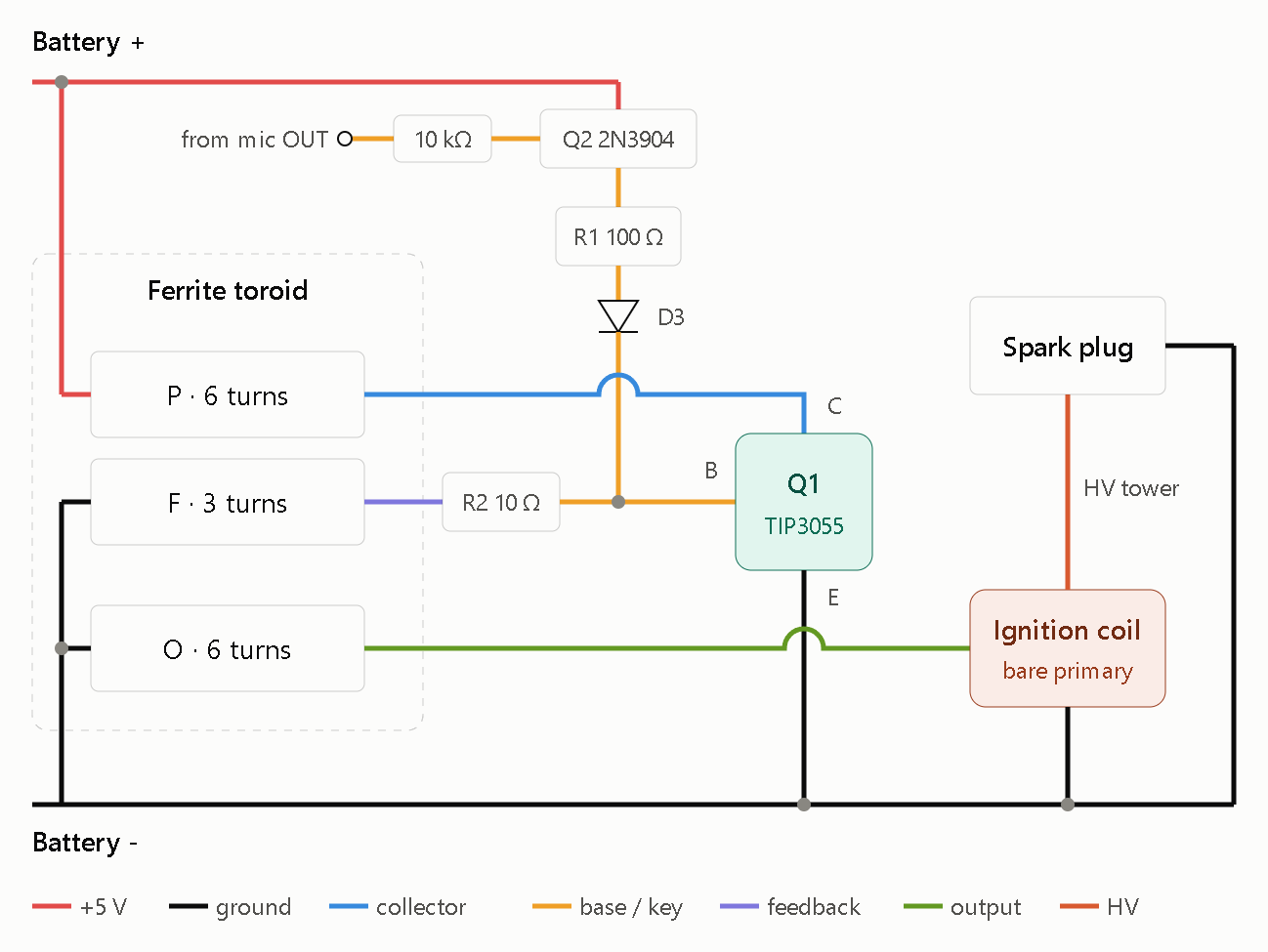
- For the first test, temporarily jumper a wire from RED to R1’s WHT lead. That bypasses Q2. Power it for 1 to 2 seconds, and you should hear a buzz and see a spark. If nothing happens, swap the F1 and F2 leads.
- Remove the jumper and build sheet 2. A clap should start the spark, and silence should stop it.
- Add sheet 3 only when you’re ready for the Pi. The Pi gets its own USB-C power, and none of its leads touch the driver’s BLK or RED except through the PC817.
Checks
- Heatsink: put an insulating pad between the TIP3055 tab and the heatsink, since the tab is the collector.
- Coil: measure the C-615’s primary resistance when it arrives, as noted above.
- Pi pins: pin 1 is the 3V3 pin, and pin 2 (5 V) sits directly across from it. Pins 9 and 11 are on pin 1’s row. Pin 9 is ground and pin 11 is GPIO17, which you’ll set high to fire the spark.
- Safety: keep your hands off the HV lead while it’s powered.
Driver
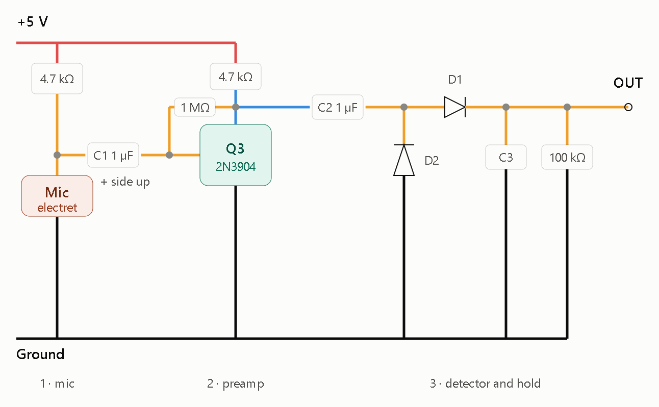
Sound-switch block that produces the OUT signal feeding Q2.
That’s the full build. Do it in this order so you can tell which part is misbehaving.
Parts to add
- Q1: TIP3055 on a heatsink
- Q2, Q3: 2N3904 (two)
- D1, D2, D3: 1N4148 (three)
- Resistors: 100 Ω (R1), 10 Ω (R2), 10 kΩ, 4.7 kΩ (two), 1 MΩ, 100 kΩ
- Caps: 1 µF (three: C1, C2, C3)
- One electret mic, a ferrite toroid, hookup wire, and a switch in the +5 V line
Build order
- Wind the toroid: P 6 turns, F 3 turns, O 6 turns, all in the same direction, with the leads tagged.
- Test the driver alone: build only the first diagram. Temporarily jumper +5 V straight to R1’s top and leave Q2 out. Power it for 1 to 2 seconds. You should hear a buzz and see a spark across the plug gap. If you get nothing, swap the F leads.
- Add the sound switch: remove the jumper, install Q2, D3 and the 10 kΩ resistor, then build the mic block. Connect its OUT terminal to the “from mic OUT” terminal on Q2. Now a clap or voice should start the spark, and silence should stop it.
- Tune it:
- Fires on its own: make the 100 kΩ bleed resistor smaller, move the mic away from the spark, and shorten the mic wires.
- Needs shouting: make the 100 kΩ bleed resistor larger, or try a 2.2 kΩ resistor in place of the preamp’s 4.7 kΩ collector resistor.