https://zchg.org/hott/late%20episodes/898%20-%2027-Jun-96%20-%20Capitailism%20vs.%20Nationalism.mp3
Lawfully. The Pen is Mightier.
How to read it
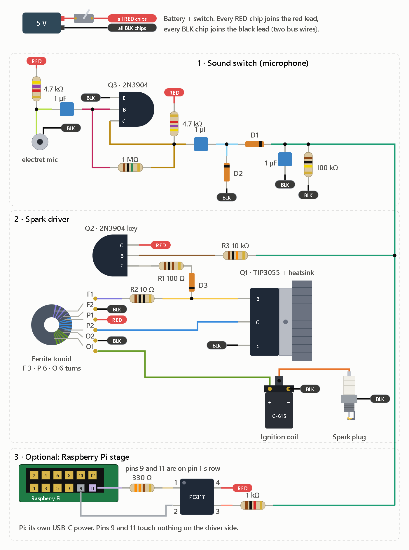
- Top: the battery and switch. Every RED chip anywhere in the drawing is soldered to the red lead, and every BLK chip to the black lead. Two bus wires, or a pair of terminal strips, make that easy.
- Section 1, sound switch: the mic, the Q3 preamp, and the diode detector. Its output is the teal OUT wire, which runs down the right edge.
- Section 2, spark driver: the toroid, Q1 on its heatsink, the coil and the plug. Q2 is the key transistor. OUT passes through R3 to Q2’s base, so sound switches the spark.
- Section 3 (dashed, optional): the Pi stage. The PC817 pulls the same OUT wire high through the 1 kΩ resistor. Without the Pi, leave this whole section out and nothing else changes.
Build order
- Build section 2 alone first. Jumper RED to the wire joining R1 and Q2’s E leg, so the key transistor is bypassed. Power it for 1 to 2 seconds. If you get no spark, swap the two F leads on the toroid.
- Remove the jumper and add section 1. A clap should start the spark.
- Add section 3 last, if you want it.
Things I haven’t verified
- Resistor and capacitor values: all are starting points that I haven’t bench-tested.
- Coil: measure the C-615’s primary resistance when it arrives. If it reads under about 1 Ω, use a strong supply.
- Toroid: it has to be ferrite. The inverter core won’t work here.
- Pi pins: the top and bottom rows of the header are drawn arbitrarily. Go by the pin numbers, not by which row looks higher. Pin 1 is the 3V3 pin, pin 2 (5 V) sits directly across from it, and pins 9 and 11 are on pin 1’s row.
- Wire colors: the white wire from Q2’s E leg to R1 is drawn light gray so it shows up on a light background. It’s still the WHT wire.
Keep your hands off the plug and HV lead while it’s powered.
Shopping list
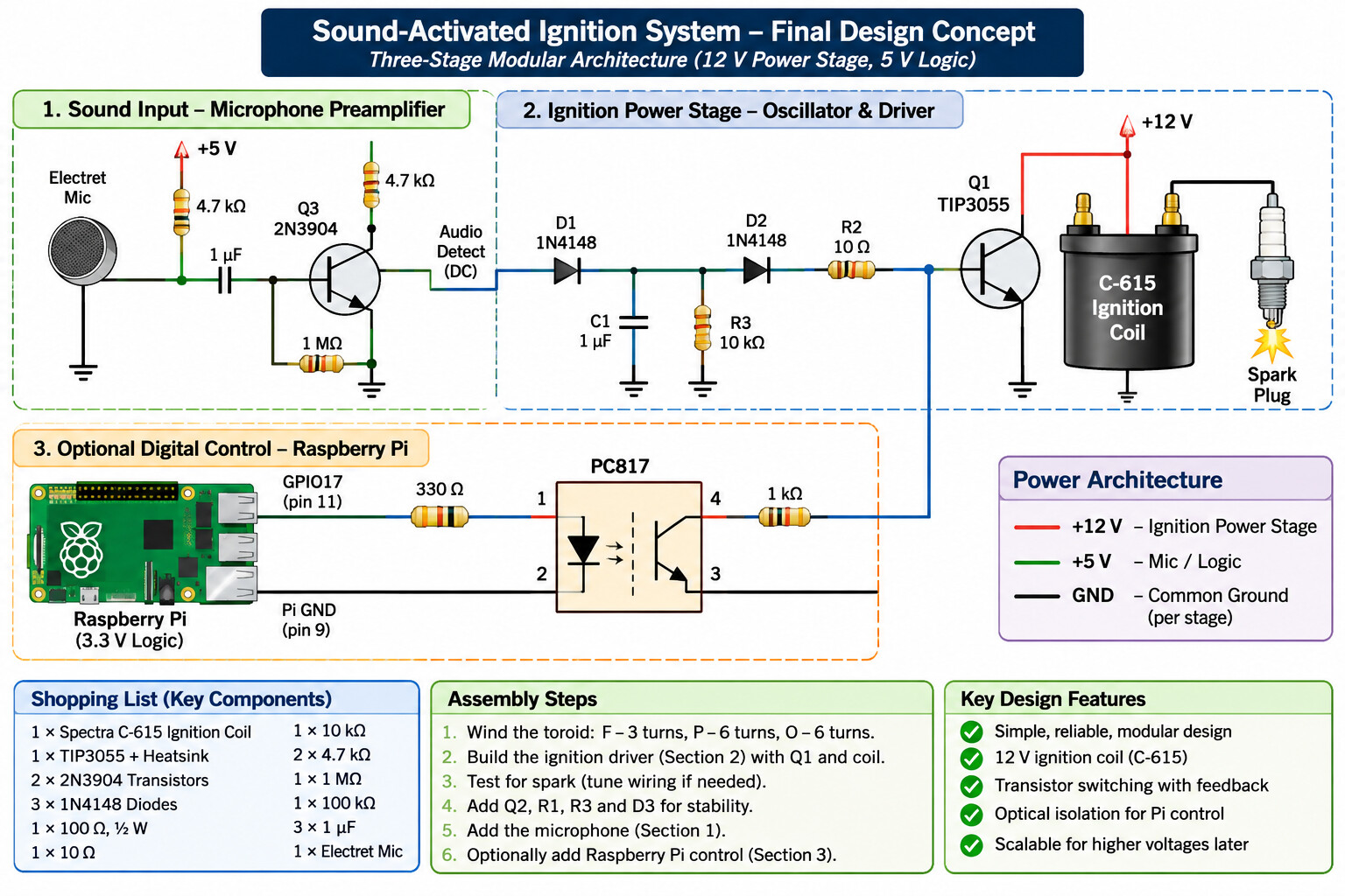
| Qty | Part | Where it goes |
|---|---|---|
| 1 | Spectra Premium C-615 ignition coil (or Standard UC-12, Echlin IC10, BWD E70) | Section 2 |
| 1 | TIP3055, with an insulating pad and a bolt-on heatsink | Q1 |
| 2 | 2N3904 | Q2, Q3 |
| 3 | 1N4148 | D1, D2, D3 |
| 1 | 100 Ω, ½ W | R1 |
| 1 | 10 Ω | R2 |
| 1 | 10 kΩ | R3 |
| 2 | 4.7 kΩ | mic bias, preamp load |
| 1 | 1 MΩ | preamp feedback |
| 1 | 100 kΩ | bleed |
| 3 | 1 µF film or ceramic | C1, C2, C3 |
| 1 | Electret mic capsule | Section 1 |
| 1 | Small ferrite toroid | Section 2 |
| 1 | Power switch, plus a 5 V supply that can give at least 2 A | Power |
| 1 | PC817, 330 Ω, 1 kΩ, and a Pi with its own USB-C supply | Section 3 only |
You already have the spark plug, plug wire and hookup wire. Get three colors of wire for the toroid windings.
Assembly order
- Wind the toroid: F 3 turns, P 6 turns, O 6 turns, all in the same direction. Tag the six leads.
- Mount Q1: bolt it to the heatsink with the insulating pad.
- Build section 2 on a board: wire the toroid, Q1, R2, the coil and the plug, and leave Q2, R1, R3 and D3 off.
- Test it: jumper RED to Q1’s base through R1. It should buzz and spark. If not, swap the F leads.
- Add the key stage: Q2, R1, R3 and D3. Remove the jumper.
- Build section 1: the mic and preamp. Join its OUT wire to R3 and check that a clap fires the spark.
- Optional Pi stage: add section 3 last.
Tell me which step you’re on and what you see, and I’ll help from there.